A full-length Ramsay Maintenance mock test + detailed explanations.
This free practice test is a full-length simulation of the Ramsay Corporation’s maintenance test, and applies to:
Ramsay MultiCrafTest / MecTest / MainTest
Amazon / Walmart Maintenance Test
The test includes 60 questions and should take you approximately 1 hour. Each question includes a detailed explanation, found in the Solutions section.
For further practice, see the Preparation section.
Have a question on any Ramsay Assessment? Contact Me!
Ramsay Maintenance Test Solved Video (10 Questions Only)
Full version (6o questions) in text below!
Free Ramsay Test (60 Questions)
Hydraulics (5 Questions)
Question 1
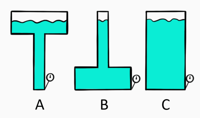
Which of the following gauges will show the highest pressure?
Gauge A
Gauge B
Gauge C
All gauges will show equal pressure
Question 2
A double-acting hydraulic cylinder drifts under load. The system valves are operating properly. What could be the cause?
Piston seal leakage
Rod seal leakage
Overfilled reservoir
Both A and B
Question 3
What most commonly causes pump cavitation?
Low inlet pressure
High inlet pressure
Air leak in the suction line
Misaligned couplings
Question 4
How should a bladder accumulator used for shock absorption be pre-charged?
With nitrogen, well below the maximum system pressure
With air, well below the maximum system pressure
With nitrogen, close to the maximum system pressure
With air, close to the maximum system pressure
Question 5
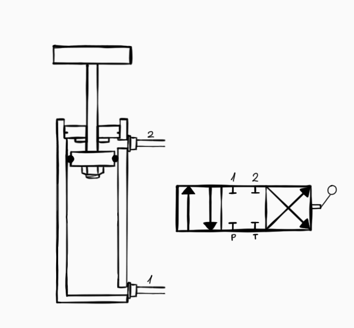
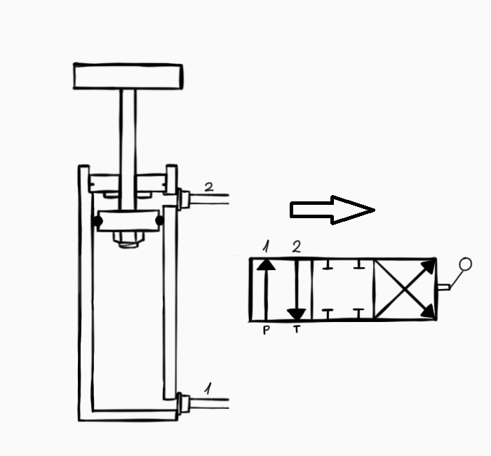
A hydraulic system includes one actuator and one directional valve, as described in the schematics below.
What will happen if the valve lever is moved to the right?
The system is in a neutral state
The actuator extends
The actuator retracts
The actuator switches between extension and retraction
Pneumatics (2 Questions)
Question 6
An air compressor has a cycle of 2 minutes. For every 30 seconds of work, the compressor must stay unpressurized for 90 seconds. What is the compressor’s duty cycle?
25%
30%
33%
75%
Question 7
Which of the following elements is used to adjust the speed of fluid in the system?
Welding (5 Questions)
Question 8
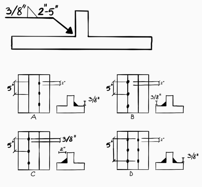
How would the weld in this blueprint be performed?
Question 9
What does the “70” in E7018 welding rod signify?
70% penetration
70K psi tensile strength
70O maximal welding angle
70 amps current required
Question 10
In what case would preheating prior to welding be most likely required?
Full Disclosure: I am affiliated with JobTestPrep. Clicking the links helps me provide you with high-quality, ad-free content.
Question 11
In the heat-affected zone…
safety gear is required
the base metal is melted
the filler metal has melted and fused into the base metal
metal has not melted
Question 12
What polarity setting is normally used for TIG?
DCEP
DCEN
AC
Both DCEN and DCEP are equally usable
Rigging (2 Questions)
Question 13
How will sling capacity change if the sling horizontal angle is reduced to 60 degrees?
Capacity is 13% higher
Capacity is 13% lower
Capacity is 26% lower
Capacity does not depend on the angle
Question 14
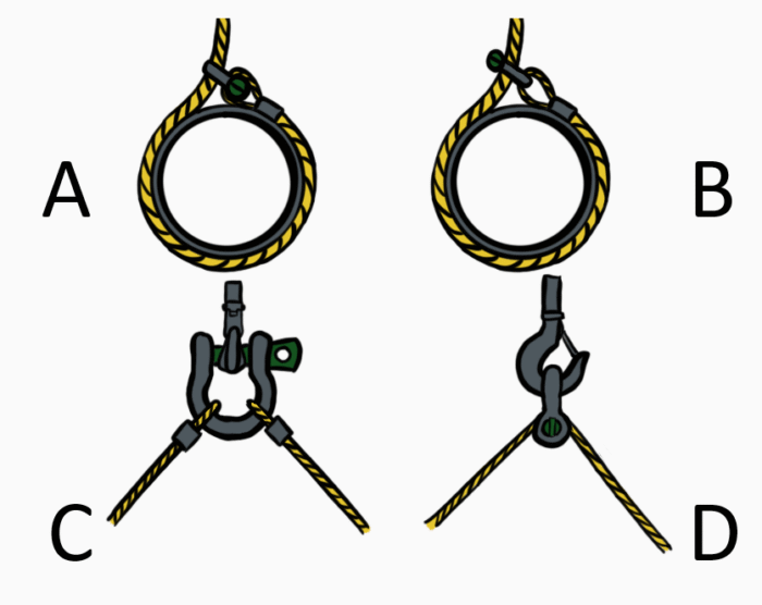
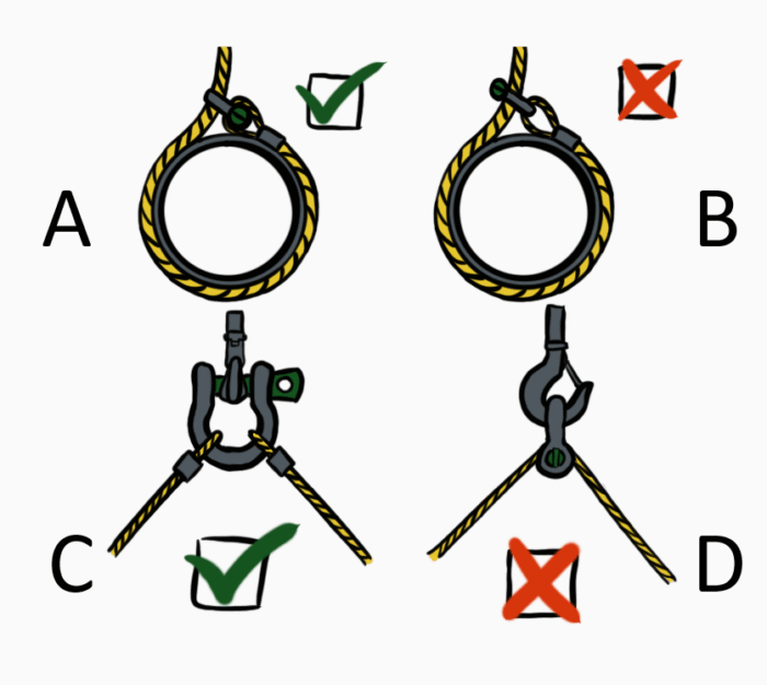
Which of these pin shackle orientations are correct?
A and C
A and D
B and C
C and D
Power Transmission (2 Questions)
Question 15
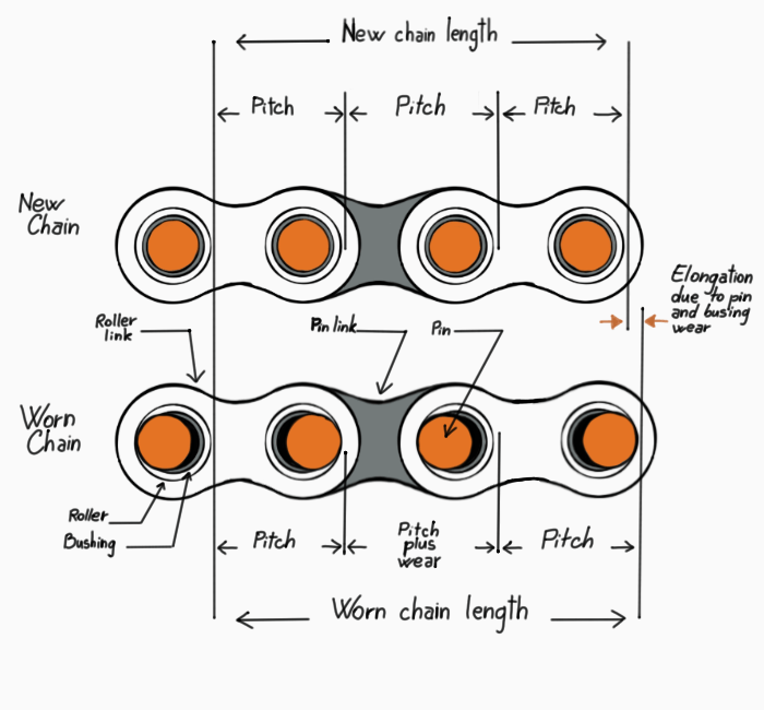
A worn roller chain has __________, compared with a new chain.
Less strands
Shortened pitch
Extended pitch
A and B
Question 16
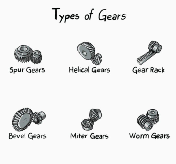
Which gear type is used for transferring motion between intersecting shafts?
Spur gear
Worm gear
Bevel gear
Helical gear
Lubrication (1 Question)
Question 17
What is the most important factor to determine a lubricant’s required viscosity index (VI) for a particular application?
The load
The rotational speed
The risk of contaminants
The temperature
Mechanical Maintenance (6 Questions)
Question 18
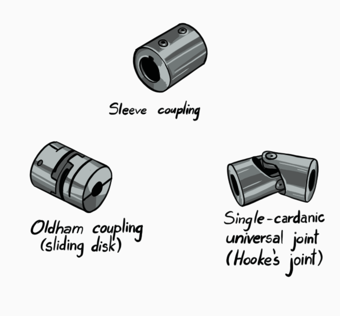
What type of coupling should you use to connect the shafts below?
Sleeve coupling
Oldham coupling
Single-cardanic universal joint
Both A and C
Question 19
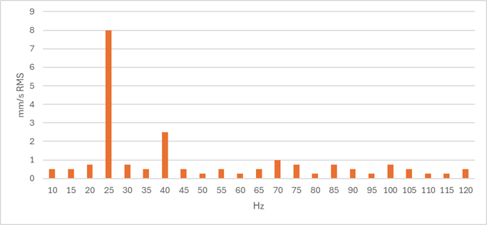
The following graph depicts the radial vibration analysis of two motors working simultaneously – Motor A at 1500 RPM and Motor B at 2400 RPM. What are the likely issue/s?
Unbalance at motor A
Misalignment at Motor B
Both A and B
No issue was detected
Question 20
What is the likely cause of a mechanical seal failure?
Over-lubrication
Rotation of the shaft-side seal face
Dry running
None of the above
Question 21
What frequencies are associated with bearing defects in preventative vibration analysis?
10-300 Hz
300-5,000 Hz
5,000-20K Hz
20K Hz +
Question 22
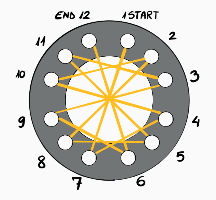
What would be the fastening sequence of the 12 bolts on the flange, according to the Legacy numbering sequence?
1,2,3,4,5,6,7,8,9,10,11,12
1,4,7,10,2,5,8,11,3,6,9,12
1,7,4,10,2,8,5,11,3,9,6,12
1,7,2,8,3,9,4,10,5,11,6,12
Question 23
What is the purpose of the LOTO procedure?
Safety
Reliability assurance
Documentation
Mechanical defect analysis
Shop Machines, Tools, and Equipment (3 Questions)
Question 24
Which of the following is INCORRECT when performing a grinder wheel ring test?
Perform the test before mounting the wheel
Tap the wheel with a metallic element
A dead sound will be heard if there is a crack in the wheel
Tap the wheel at a 45-degree angle from the centerline
Question 25
Which of these describes a proper match between a tool steel grade and its application?
A W-series tool steel for a high-temperature application
An S-series tool steel for a jackhammer chisel
An S-series tool steel for bearing balls
An H-series tool steel for low-friction tubes
Question 26
When should a blue threadlocker be used?
For preassembled parts
For permanent joints
When bolts require daily removal
When bolts require occasional removal
Pumps and Piping (6 Questions)
Question 27
What is the negative effect of entrapped air in piping?
Reduced flow
Higher pressure in the piping
Possible damage to components when air is released
Both A and C
Question 28
While externally inspecting an end-suction pump, you find that the bolts of the outlet flange and the hold-down bolts are distorted. What can be the cause?
Impeller imbalance
Pipe strain
Suction-side cavitation
Clogged strainer
Question 29
Insufficient NPSH may cause:
Head losses
Air entrapment
Acidity
Cavitation
Question 30
When is this element likely to be used in a piping system?
When highly viscous fluids are pumped
At extreme thermal ranges
At high pressure
With HAZMAT
Question 31
When would you prefer installing a centrifugal pump over a positive displacement pump?
At low flow rates
When pumping highly viscous fluids
When frequent changes in flow speed are required
None of the above
Question 32
Adding a stage to a multi-stage centrifugal pump increases:
Discharge flow rate
Discharge pressure
Suction pressure
Both A and B
Need extra practice? Check out the recommended Ramsay maintenance test prep course by JobTestPrep.
What is the main purpose of a flame sensor in a combustion system?
Preventing gas leaks
Assuring proper temperature
Increasing air flow
Maintaining constant electric current
Question 34
A common result of a fuel-lean mixture is:
A lower combustion temperature
Production of carbon monoxide
Black smoke
None of the above
Question 35
Which of the following decreases thermal draft?
A higher chimney temperature
A higher outside temperature
A higher chimney
None of the above
Motors (4 Questions)
Question 36
In a synchronous motor, the slip is:
10% or higher
dependent on the motor speed
higher than in an induction motor
0
Question 37
In what case would you choose using a DC series-wound motor?
When constant operating speed is required
When precise variations in operating speed are required
When high starting torque is required
Both A and C
Question 38
Of the following, which is the most important factor to consider when designing motor protective switchgear?
hp
F.L.A.
S.F
The motor’s characteristics hardly affect switchgear selection
Question 39
What might be the cause of motor overheating?
Motor spinning idle
Reverse phase sequence
Motor operating under low load
Insufficient voltage
Control Circuits (2 Questions)
Question 40
What is the purpose of the “M” contact in the following circuit?
Overload protection
Increasing the amount of electrical current through the system
Seal in contact
Timed start-up delay
Question 41
In a system that consists of two motors, only one should operate at any given moment. Which component is normally used to achieve that?
Interlock
VFD
Pilot indicator
Holding contact
Schematics and Print Reading (3 Questions)
Question 42
Fill in the blanks in the correct order:
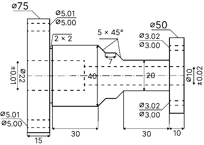
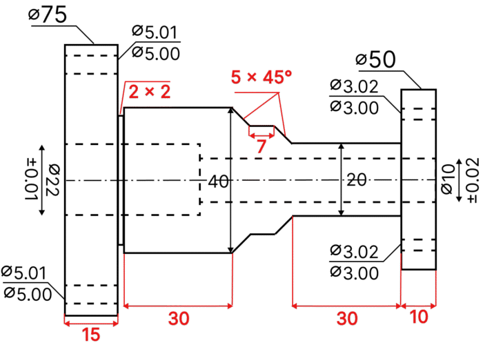
The 10 mm diameter is a ______ with a 0.02 mm ______. The ______ is 5 mm long at a 45-degree angle. The 22 mm diameter, on the other hand, is a _______. The element also includes a 2 mm deep ________.
chamfer, diameter, undercut, recess, through hole.
through hole, radius, undercut, recess, bevel.
recess, tolerance, chamfer, through hole, undercut.
through hole, tolerance, chamfer, recess, undercut.
Question 43
What is the overall length of the piece?
85 mm
104 mm
156 mm
204 mm
Question 44
Which diameter requires the highest level of precision?
3 mm
5 mm
10 mm
22 mm
Digital Electronics (1 Question)
Question 45
Which of the following gates has the same output as:
Power Supplies (1 Question)
Question 46
What is the purpose of a rectifier in a power supply?
Increasing voltage
Converting AC to DC
Filtering noise
Regulating current
Computers & PLC (4 Questions)
Question 47
The minimal number of AND and OR gates required for the logic diagram equivalent to the PLC ladder above is:
2 AND gates and 2 OR gates
2 AND gates and 3 OR gates
3 AND gates and 2 OR gates
3 AND gates and 3 OR gates
Question 48
In a PLC diagram, an N.C. contact could represent:
A start button
An emergency stop button
A gas detector in a furnace
Both B and C are correct
Question 49
In ladder logic, the leftmost elements should normally be:
Safety and stop interlocks
Complex logic elements (e.g., timers)
Output coil
The order of the elements along the rung does not matter
Question 50
Fill in the blanks correctly:
When terminating a _______ ethernet cable through an RJ45 connector, you should use _________ on __________.
Straight through, T568A or T568B, both sides.
Crossover, T568A or T568B, both sides.
Straight through, T568A on one side and T568B on the other.
Crossover, only T568B, both sides.
Test Instruments (2 Questions)
Question 51
When using a clamp meter to measure AC current:
Clamp the hot and neutral wires together
Clamp only one wire at a time
Ground the meter before measurement
Both B and C
Question 52
What does a beep typically indicate when using a multimeter in continuity mode?
An open circuit between measured points
High resistance between measured points
Low resistance between measured points
Voltage difference between measured points
Basic AC/DC Theory (3 Questions)
Question 53
What is the power in the following circuit?
6W
12W
24W
48W
Question 54
A sinusoidal AC wave has a peak value of 220 V and an RMS of 155 V. What is the wave’s frequency?
1.4 Hz
65 Hz
110 Hz
Cannot be determined
Question 55
What current flows through resistor 3 in the following circuit?
0.143 A
0.286A
0.347 A
0.429 A
Power Distribution (2 Questions)
Question 56
A step-down transformer has 3000 turns on the primary coil. The primary voltage is 1000 V. This means that the secondary coil could have _____ turns and that the secondary voltage is ____ V.
300, 1000
300, 100
6000, 2000
Both B and C are correct
Question 57
Transferring a single-phase system into a 3-phase system will NOT allow:
Reduced conductor size
Increased power
Reduced overall wiring length
Stabler output power
Electrical Maintenance (3 Questions)
Question 58
Which of the following faults cannot be detected using infrared electrical inspection?
Open circuits
Loose connections
Overloaded circuits
None of the above
Question 59
Which of the following components needs to be discharged before performing maintenance?
Resistors
Relays
Transformers
Capacitators
Question 60
A circuit breaker has tripped. What should you do immediately afterwards?
Replace the breaker with a higher rated one
Inspect the circuit for overload or other faults
Reset the breaker
Wire a bypass around the breaker
Need extra practice? Check out the recommended Ramsay maintenance test prep course by JobTestPrep.
Which of the following gauges will show the highest pressure?
Gauge A
Gauge B
Gauge C
All gauges will show equal pressure
Explanation
This phenomenon is called “the hydrostatic paradox”. In a static fluid, the pressure at any given point is determined only by the height of fluid above that point (i.e., depth).
Mathematically, Pascal’s law can be described as:
P = p x g x H
Where:
P is the hydrostatic pressure
p is the fluid density
g is the acceleration of gravity
H is the height of fluid above the point of measurement
p and g are constants, so the only variable which determines P is H.
Question 2
A double-acting hydraulic cylinder drifts under load. The system valves are operating properly. What could be the cause?
Piston seal leakage
Rod seal leakage
Overfilled reservoir
Both A and B
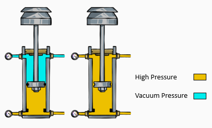
Explanation
A cylinder drift is a physical movement of the cylinder when supposed to be held in position. This is caused by hydraulic fluid bypassing the closed circuit.
Contrary to the common misconception, a piston leak does not cause drift. That is because the pressure on both sides of the piston is equalized, so the cylinder remains in a hydraulic lock.
However, a rod seal leakage allows the fluid to leave the system, reducing the pressure and making room for the rod to drift all the way down to the bottom of the cylinder.
As for answer C – an overfilled reservoir does not create a path for oil to bypass the close circuit and hence does not cause drift.
A functioning cylinder (left) vs. a cylinder with a piston seal leakage (right)
Question 3
What most commonly causes pump cavitation?
Low inlet pressure
High inlet pressure
Air leak in the suction line
Misaligned couplings
Explanation
Cavitation is when air bubbles collapse on the pump’s inlet side. This initially happens when low inlet pressure causes the air dissolved in the hydraulic fluid to vaporize. When these air bubbles reach an area of high pressure again, they collapse, damaging the machinery.
Air leak in the suction line may cause air entrainment – external oil being sucked into the hydraulic system. This phenomenon is different from cavitation.
Misaligned couplings may cause mechanical wear but are unrelated to cavitation.
Question 4
How should a bladder accumulator used for shock absorption be pre-charged?
With nitrogen, well below the maximum system pressure
With air, well below the maximum system pressure
With nitrogen, close to the maximum system pressure
With air, close to the maximum system pressure
Explanation
Accumulators are components used to store hydraulic energy – i.e., fluid volume under pressure. As such, one of their main purposes is to serve as protection mechanisms – a cushion to absorb and dampen shock.
To serve this purpose, gas-charged accumulators, such as bladder or diaphragm accumulators, are pre-charged with gas to have this hydraulic energy stored.
When an accumulator is used for shock absorption, it should operate with very low levels of oil, so that it responds rapidly and effectively to pressure spikes. Therefore, it should be pre-charged to a pressure close to the maximum system pressure.
Finally, accumulators are pre-charged with nitrogen rather than with air. Compressed air may react violently to hydrocarbons, resulting in fire or an explosion.
Question 5
A hydraulic system includes one actuator and one directional valve, as described in the schematics below.
What will happen if the valve lever is moved to the right?
The system is in a neutral state
The actuator extends
The actuator retracts
The actuator switches between extension and retraction
Explanation
The given schematic presents a 3-position, 4-way directional valve. The P and T labels represent pump and tank, respectively.
1 and 2 represent the work ports connected to the cylinder. In our case, 1 represents the cap end port, while 2 represents the rod end port.
When the lever is moved to the right, the valve moves to the left position – the fluid now flows from the pump (P) to the cap end (1) and from the rod end (2) to the tank (T).
Therefore, pressure forms in the cap end, extending the actuator.
Conversely, when the lever is moved to the left, the valve moves to the right position, and the fluid now flows from the pump to the rod end and from the cap end to the tank. The actuator retracts.
When the valve is in the center position, the system is in a neutral state.
Pneumatics (2 Questions)
Question 6
An air compressor has a cycle of 2 minutes. For every 30 seconds of work, the compressor must stay unpressurized for 90 seconds. What is the compressor’s duty cycle?
25%
30%
33%
75%
Explanation
A compressor’s duty cycle is calculated as the time, per cycle, in which the compressor can deliver pressurized air divided by the total cycle time. So, in our case:
DC = 30 / 120 = 25%
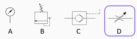
Question 7
Which of the following elements is used to adjust the speed of fluid in the system?
Explanation
Symbol A represents a gauge. Gauges are used only for measurements and do not control the flow.
Symbol B represents a relief valve. Relief valves are safety devices used to relief excess pressure in the system. It does not regulate the flow speed.
Symbol C represents a pilot-operated check valve. Standard check valves allow only one-directional flow. However, pilot-operated check valves allow flow in the opposite direction when a pilot signal is applied.
Symbol D represents an adjustable flow control valve (i.e., a needle valve). These valves are used to regulate the speed of fluid.
Welding (5 Questions)
Question 8
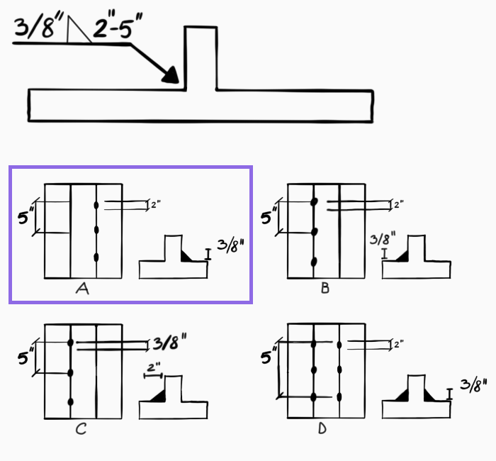
How would the weld in this blueprint be performed?
Explanation
Let’s analyze the various elements of welding symbols in this question:
Arrow – In this case, symbols appear above the arrow, which means on the otherside of the joint.
Triangle – the triangle indicates a fillet The 3/8 indicates the weld size.
Length and Pitch – the length and pitch values are 2” and 5”, respectively. This means that a 2” long fillet weld will be applied every 5”.
Question 9
What does the “70” in E7018 welding rod signify?
70% penetration
70K psi tensile strength
70O maximal welding angle
70 amps current required
Explanation
The AWS (American Welding Society) electrode classification includes 5 components. They are described in the table below, alongside the practical example E7018.
Section
Meaning
Example (E7018)
Prefix (Letter)
Product family
E = electrode (SMAW)
First 2-3 digits
Minimum tensile strength in ksi (1,000 psi)
70 = 70 ksi = 70K psi
Third digit
Welding position
1 = all positions
Fourth digit
Type of flux covering and suitable current/polarity
8 = low-hydrogen iron powder
Suffix digit
Special properties (optional)
None
So, the 70, in an “E7018” welding rod stands for a minimal tensile strength of 70 ksi, or 70K psi.
Question 10
In what case would preheating prior to welding be most likely required?
When a high deposition rate is required
When welding thin elements
In highly restrained joints
Preheating is always required in welding
Explanation
Preheating is heating the base metal prior to welding. The most noticeable effect of preheating is a slower colling rate, which leads to a reduced risk for cracks or fractures. Not every welding requires preheating – it depends on the particular characteristics of the job.
Deposition rate is the rate in which metal is added to the weld. It is determined by a variety of factors such as the amperage, the electrode, wire feed speed, etc. Preheating does not affect deposition rate. Therefore, response A is incorrect.
Cracks and fractures are more likely to happen in thicker elements. These tend to have larger strains, as well as higher risk of existing inner fractures. Hence, answer B is incorrect.
Welding highly restrained joints may leave residual stress, which makes the weld more sensitive to cracking. In this case, therefore, preheating is recommended.
Question 11
In the heat-affected zone…
safety gear is required
the base metal is melted
the filler metal has melted and fused into the base metal
metal has not melted
Explanation
The heat-affected zone (HAC) is the area in which the base metal hasn’t melted, but the heat has nonetheless changed its properties and microstructure. These altered properties may be tensile strength, micro-cracks, susceptibility to corrosion, etc.
The area where the base metal is melted and is to be infused with filler metal is called “the weld pool”. The area in which both the base and filler metal have fused is called “the fusion zone”.
Question 12
What polarity setting is normally used for TIG?
DCEP
DCEN
AC
Both DCEN and DCEP are equally usable
Explanation
In all types of GMAW (Gas Metal Arc Welding), the welding machine forms an electric arc between the electrode and the workpiece.
Three polarity possibilities exist:
DCEP (DC Electrode Positive) – the electrode is connected to the positive side of the arc, and the workpiece to the negative side.
DCEN (DC Electrode Negative) – the electrode is connected to the negative side of the arc, and the workpiece to the positive side.
Alternating Current (AC) – alternates between the two aforementioned states.
At its core, the main consequence of choosing polarity is where the heat is concentrated.
In an electric arc, most heat (~70%) is concentrated at the positive side (cathode), while the remaining 30% is at the negative side (anode).
When the electrode is positive, it results in a stabler arc, higher deposition rate, and less spatter. Therefore, this is the standard setting for most GMAW welds.
However, the purpose of TIG (Tungsten Inert Gas) welding is to heat the workpiece with the non-consumable tungsten electrode. Excessive heat at the electrode can destroy it. Therefore, when using TIG welding, DCEN is the preferable polarity in almost every case.
AC polarity is used mostly when welding aluminum, due to its cleaning effect.
Rigging (2 Questions)
Question 13
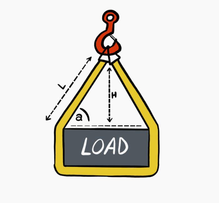
How will sling capacity change if the sling horizontal angle is reduced to 60 degrees?
Capacity is 13% higher
Capacity is 13% lower
Capacity is 26% lower
Capacity does not depend on the angle
Explanation
When decreasing a sling angle below the vertical lift, the stress on the sling leg increases. That is because the sling leg now must support the vertical load in addition to the horizontal loads formed by the angle.
Therefore, the overall stress in the sling increases.
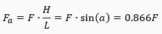
To calculate the capacity of each sling leg under angle (a), you can either use the sling leg length (L) and height (H) or the sine of the angle:
So, the new sling capacity is ~87% of the original.
Question 14
Which of these pin shackle orientations are correct?
A and C
A and D
B and C
C and D
Explanation
When rigging using a shackle pin, the pin should be placed in the static point. Placing moving parts over the pin may cause it to rotate and unscrew. In the image above, the pin is adjacent to the moving parts in B (choker sling) and D (bridle hitch).
Power Transmission (2 Questions)
Question 15
A worn roller chain has __________, compared with a new chain.
Less strands
Shortened pitch
Extended pitch
A and B
Explanation
The constant movement of the roller chain around the sprocket creates constant friction and wear in the pins and bushings. This increases the chain’s pitch and causes the chain to elongate.
‘Pitch’ is the distance between two adjacent pins.
The number of strands in a chain is determined during manufacturing and does not change with use.
Question 16
Which gear type is used for transferring motion between intersecting shafts?
Spur gear
Worm gear
Bevel gear
Helical gear
Explanation
Spur and helical gears are used to transfer loads between parallel shafts. Bevel gears are used in intersecting shafts, and worm gears are used for non-parallel, non-intersecting shafts.
Lubrication (1 Question)
Question 17
What is the most important factor to determine a lubricant’s required viscosity index (VI) for a particular application?
The load
The rotational speed
The risk of contaminants
The temperature
Explanation
A lubricant’s viscosity index is defined as the change in its viscosity due to temperature. The higher the VI, the less viscosity changes with temperature.
As such, a lubricant with a high viscosity index will maintain its viscosity over a high range of temperature, whereas a low VI lubricant may work properly in low temperatures but rapidly lose viscosity as the heat rises. This may result in increased friction and mechanical wear due to film loss.
Note that load and speed are two factors that contribute to the system’s eventual temperature, but the determining factor is the temperature.
Mechanical Maintenance (6 Questions)
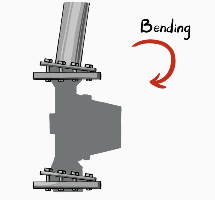
Question 18
What type of coupling should you use to connect the shafts below?
Sleeve coupling
Oldham coupling
Single-cardanic universal joint
Both A and C
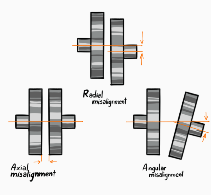
Explanation
The image shows two shafts with radial misalignment (aka parallel misalignment) – when the two shafts are parallel but are not on a common center line.
Of the given options, an Oldham coupling (a sliding disk coupling) is designed to address applications where shafts have radial misalignment.
On the other hand, a sleeve coupling is a rigid coupling, requiring perfect collinearity between shafts.
A single-cardanic universal joint (aka Hooke’s joint) is used for applications where shafts have an angular misalignment (the shafts are not parallel).
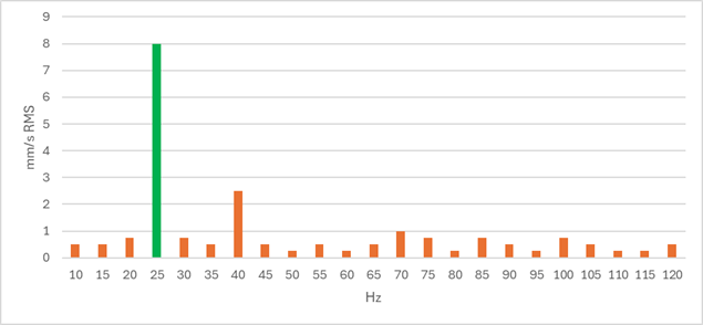
Question 19
The following graph depicts the radial vibration analysis of two motors working simultaneously – Motor A at 1500 RPM and Motor B at 2400 RPM. What are the likely issue/s?
Unbalance at motor A
Misalignment at Motor B
Both A and B
No issue was detected
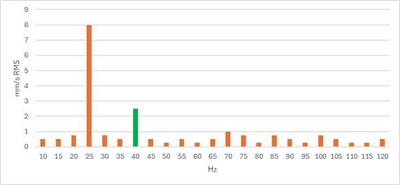
Explanation
The graph shows the frequency spectrum of both motors’ vibration analysis.
From the graph, it is clear that the vibrations at the 25 Hz frequency are the strongest, as shown by their exceptionally high amplitude (8 mm/s RMS).
Note that 1 Hz is defined as one cycle per second. So, in the case of a rotating machine like a motor, a 25 Hz frequency is equal to 1,500 RPM, since 25 x 60 = 1,500.
To sum it up, the vibration analysis shows high vibrations on the x1 RPM frequency, which is typical for unbalance.
On the other hand, Motor B shows a normal operation pattern with a moderate peak at its x1 RPM frequency (40 Hz = 2,400 RPM).
In case of a misalignment, decreasingly high peaks will be seen in other harmonics of the motor’s frequency – x1 RPM, x2 RPM, etc. So, for instance, misalignment in Motor B will show peaks at 40 Hz, 80 Hz, and 120 Hz that become progressively “lower”.
Question 20
What is the likely cause of a mechanical seal failure?
Over-lubrication
Rotation of the shaft-side seal face
Dry running
None of the above
Explanation
Mechanical seals are composed of two faces – one rotates with the shaft and the other remains stationary in the pump housing.
To work properly, mechanical seals need a thin layer of hydrodynamic film. This both allows them to do their job sealing and reduces wear and tear. In pumps, the seal lubricant is normally the pumped fluid itself.
Therefore, mechanical seals are highly likely to fail in a dry-running pump, causing both leakage and shortened lifespan of the seal itself.
Need extra practice? Check out the recommended Ramsay maintenance test prep course by JobTestPrep.
What frequencies are associated with bearing defects in preventative vibration analysis?
10-300 Hz
300-5,000 Hz
5,000-20K Hz
20K Hz +
Explanation
When assessing bearing defects using vibration analysis, we can divide the frequency spectrum into 4 zones. We’ll go backwards for explanatory purposes.
Zone 4 (20K Hz +)
Some high-frequency techniques are able to identify microscopic bearing defects in this stage (e.g., cracks in the internal balls). However, these are rather weak indications that a bearing failure may happen in the future, and it is therefore not recommended to carry out any substantial maintenance at this point.
Instead, it is recommended to ensure proper lubrication of the bearings and monitor their state regularly.
Zone 3 (5,000 – 20K Hz)
This is the range of the bearing’s natural frequency. Similar to zone 4, bearing faults can be detected in this range at their very early stage – too soon to carry out substantial maintenance.
Zone 2 (300 – 5,000 Hz)
This range includes the bearing’s operation frequencies:
Ball Pass Frequency Outer Race (BPFO)
Ball Pass Frequency Inner Race (BPFI)
Ball Spin Frequency (BSF)
Fundamental Train Frequency (FTF)
These frequencies (especially the first three) and their harmonics are detected in the case of bearing defect. Hence, this is the range in which peak frequencies will be most closely associated with bearing preventative maintenance – a clear indication for bearing defect but not yet at a critical state.
Zone 1 (<300 Hz)
Bearing defects will normally not be identified in this range, and it is used to detect macroscopic issues such as unbalance or misalignment.
Question 22
What would be the fastening sequence of the 12 bolts on the flange, according to the Legacy numbering sequence?
1,2,3,4,5,6,7,8,9,10,11,12
1,4,7,10,2,5,8,11,3,6,9,12
1,7,4,10,2,8,5,11,3,9,6,12
1,7,2,8,3,9,4,10,5,11,6,12
Explanation
The Legacy numbering sequence is one ‘best practice’ method to make sure that stress is evenly distributed across the flange when tightening the bolts. Tightening adjacent bolts without redistributing the load by tightening the opposite ones may damage the flange, but more likely, the gasket beneath it.
Therefore, in this star-shape pattern, bolts are tightened in a progressive sequence of opposing bolts.
To easily remember that sequence, all you need to do is to remember the first four digits. Then, arrange them vertically and add “1” to each digit for the second column. Repeat the process for the third column:
1
2
3
7
8
9
4
5
6
10
11
12
Rearrange the table, and you have the full sequence 1,7,4,10,2,8,5,11,3,9,6,12.
It should be noted that a simpler method, the quadrant pattern, exists. In this pattern, the next loose bolt in any given quadrant will be tightened. However, this method is used only in flanges of 16 or more bolts.
Question 23
What is the purpose of the LOTO procedure?
Safety
Reliability assurance
Documentation
Mechanical defect analysis
Explanation
The Loco out, tag out (LOTO) procedure is a safety procedure. It is used to ensure that dangerous equipment is de-energized before any maintenance work and remains de-energized until it is completed.
The name is derived from the process of both locking energy sources to prevent them from being turned on by mistake and tagging them to indicate that they should remain closed.
Shop Machines, Tools, and Equipment (3 Questions)
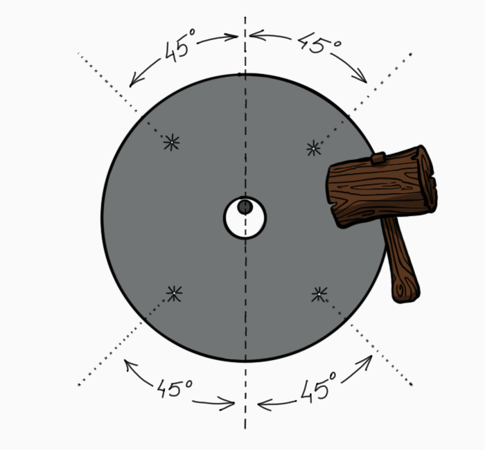
Question 24
Which of the following is INCORRECT when performing a grinder wheel ring test?
Perform the test before mounting the wheel
Tap the wheel with a metallic element
A dead sound will be heard if there is a crack in the wheel
Tap the wheel at a 45-degree angle from the centerline
Explanation
The purpose of a ring test is to inspect the grinder wheel for cracks before mounting it on the grinder. The cracks can be identified by the sound of the wheel when tapped.
To perform the test, hang the wheel from the finger or another non-metallic pin, and tap it with a wooden or plastic in four places, 45 degrees from the centerline.
An intact wheel will generate a clear, resonant sound, while a cracked wheel will generate a short, dead sound.
Since we want to be sure that it is the sound of the wheel we are hearing, we should use non-metallic elements to perform the tapping and the hanging. Metallic elements can resonate and create sounds that could distract us from the actual sound of the wheel.
Question 25
Which of these describes a proper match between a tool steel grade and its application?
A W-series tool steel for a high-temperature application
An S-series tool steel for a jackhammer chisel
An S-series tool steel for bearing balls
An H-series tool steel for low-friction tubes
Explanation
Tool steel is a type of steel specifically designed for manufacturing tools. These steels are categorized into several groups, each with its designated purposes and performance requirements.
W-series tool steel stands for water-hardening. That refers to the heat treatment the steel undergoes, being quenched in water. This causes rapid cooling, which results in high hardness but low toughness. This makes the still very brittle and susceptible to heat. Therefore, this type of steel will not operate well in high temperatures.
A word on hardness vs. toughness: Hardness is the ability to resist local plastic deformation, whereas toughness is the ability to absorb impact energy. For instance, glass has relatively high hardness but very low toughness. That’s why you could (theoretically) make very sharp glass knives, but not a hammer.
S-series stands for shock-resisting. This type of tool steel contains low levels of carbon, which makes it very tough and ideal for applications where resistance to shock is required, as in a sledgehammer’s chisel. On the other hand, it makes it unsuitable for elements that require hardness and high resistance to abrasion, such as bearing balls.
H-series stands for hot work. This steel is alloyed with chromium, molybdenum, or tungsten to create high heat resistance and very high hardness. These factors, alongside the coarse microstructure, make it unsuitable for smooth, polished surfaces, as in a low-friction tube.
Note that we have not mentioned all tool steel types in this explanation, only those that are mentioned in this question.
Question 26
When should a blue threadlocker be used?
For preassembled parts
For permanent joints
When bolts require daily removal
When bolts require occasional removal
Explanation
Threadlockers are adhesives applied to the threads of nuts and bolts to prevent them from loosening due to stress or vibration. The threadlocker’s color indicates its strength:
Purple – low strength. Bolts can be easily removed by hand tools. This threadlocker suits answer C.
Blue – medium strength. Bolts can be removed with hand tools while applying some force. This threadlocker suits answer D.
Red – high strength. Generally used for permanent joints, as bolts can only be removed by applying localized heat. This threadlocker suits answer B.
Green – medium to high strength + wicking. Its strength is between that of the blue and red threadlockers, but it also has wicking capacity. Therefore, it can be applied to preassembled fasteners and wick down the threads through capillary action. This threadlocker suits answer A.
Pumps and Piping (6 Questions)
Question 27
What is the negative effect of entrapped air in piping?
Reduced flow
Higher pressure in the piping
Possible damage to components when air is released
Both A and C
Explanation
Entrapped air in piping causes several problems. Most commonly, air lodges at high points in the piping, causing less area available for flow. This causes reduced flow and suboptimal pump performance.
Another problem, which may even be more acute, occurs when the pocket of entrapped air reaches the outlet and is vented out. Since gas is far less dense than liquid, it leaves the system at a much faster rate, causing water to quickly rush in to replace it.
This results in a momentary velocity spike that can damage system parts.
Question 28
While externally inspecting an end-suction pump, you find that the bolts of the outlet flange and the hold-down bolts are distorted. What can be the cause?
Impeller imbalance
Pipe strain
Suction-side cavitation
Clogged strainer
Explanation
Pipe strain is caused by misalignment between the pump’s inlet and outlet to the corresponding pipe flanges. This misalignment, often the result of poor pipe support, causes side loads and bending moments that lead to damage to the pump components.
Impeller imbalance, cavitation, and clogged suction strainer may cause damage to internal pump components. They do not create the axial or lateral loads on the inlet required to bend the flange bolts or the hold-down bolts.
Question 29
Insufficient NPSH may cause:
Head losses
Air entrapment
Acidity
Cavitation
Explanation
NPSH is Net Positive Suction Head – the difference between the pump’s absolute suction pressure and the vapor pressure of the pumped liquid.
When there is not enough NPSH in the system, some of the pump liquid will turn into vapor. These vapor bubbles collapse at the area of high pressure near the impeller, and the resulting shockwaves damage the impeller and other components over time. This phenomenon is known as cavitation.
As was explained in previous questions, cavitation and air entrapment are not the same. Unlike cavitation, which results from vaporized fluid, air entrainment is the result of external air entering the system. This phenomenon has negative consequences of its own, but it is unrelated to NPSH.
Acidity depends on the properties of the pumped fluid more than anything.
Head losses exist in any pumping system. They occur mostly along the pipes, and depend on the pipe’s shape, size, material, and length. Head losses are a considerable factor in calculating NPSH. However, a low NPSH is the result of substantial head losses, not their cause.
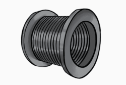
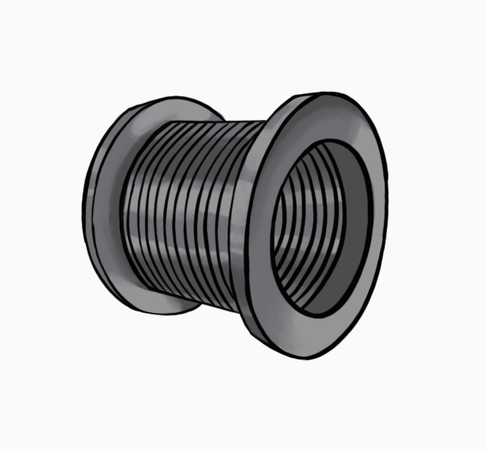
Question 30
When is this element likely to be used in a piping system?
When highly viscous fluids are pumped
At extreme thermal ranges
At high pressure
With HAZMAT
Explanation
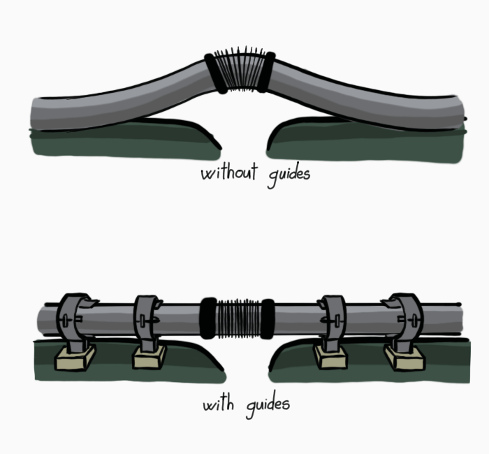
The element in the image is a bellows expansion joint.
Expansion joints are flexible joints used to absorb loads due to piping thermal expansion and contraction.
Higher pressure thrust (which may result from highly viscous fluids or highly pressurized pipes) is not absorbed by expansion joints. Moreover, the installation of expansion joints along the pipeline requires the installation of guides to prevent the pipes from buckling due to the deflection.
Question 31
When would you prefer installing a centrifugal pump over a positive displacement pump?
At low flow rates
When pumping highly viscous fluids
When frequent changes in flow speed are required
None of the above
Explanation
Positive displacement pumps operate by drawing a fixed amount of fluid into a cavity and transferring it from the suction to the discharge. These pumps are suitable for highly viscous fluids. Their mechanism allows little flexibility in flow rates, and they tend to operate at low, constant flow rates.
Centrifugal pumps operate via a rotating impeller that draws the fluid into the pump and discharges it at increased velocity. These pumps have high friction losses when working with viscous fluids and are therefore unsuitable for this purpose. However, their mechanism enables them to quickly shift flow rates, and they can operate at a variety of speeds.
Question 32
Adding a stage to a multi-stage centrifugal pump increases:
Discharge flow rate
Discharge pressure
Suction pressure
Both A and B
Explanation
Multi-stage centrifugal pumps contain several impellers in series. Each impeller adds head (pressure) to the previous stage, thus increasing the overall discharge pressure.
Since all impellers share the same flow path, the same amount of liquid passes through every impeller. Therefore, the discharge flow rate remains mostly unchanged.
This characteristic of multi-stage centrifugal pumps makes them ideal for applications where pumping liquids from low-pressure to high-pressure systems is required, while maintaining the flow rate. A common example is transporting drinking water in tall apartment buildings.
Adding stages to the pump increases pressure on the discharge side, so suction pressure is unaffected.
Combustion (3 Questions)
Question 33
What is the main purpose of a flame sensor in a combustion system?
Preventing gas leaks
Assuring proper temperature
Increasing air flow
Maintaining constant electric current
Explanation
Flame sensors detect the presence of flame inside a furnace. Once the sensor fails to detect flame, it will send an appropriate signal to the furnace’s control board, which will, in turn, shut down the fuel supply. That’s because when fuel/gas is released but isn’t ignited, it means that it either escapes the system or builds up inside.
Question 34
A common result of a fuel-lean mixture is:
A lower combustion temperature
Production of carbon monoxide
Black smoke
None of the above
Explanation
Every combustion engine requires a proper balance between air and fuel to run properly.
A fuel-lean mixture means there is more air than needed, while a fuel-rich mixture means there is more fuel than needed.
Typically, in rich mixtures, the relative lack of oxygen causes incomplete combustion. This results in:
Production of carbon monoxide (CO) instead of the carbon dioxide (CO2) produced in complete combustion.
Lower combustion temperature, as less chemical energy is released in incomplete combustion.
The unburned fuel may appear as black smoke.
In lean mixtures, on the other hand, the combustion is complete, but it may result in different issues such as unnecessarily high temperatures and jerking motions of the engine.
Question 35
Which of the following decreases thermal draft?
A higher chimney temperature
A higher outside temperature
A higher chimney
None of the above
Explanation
Draft is the current of air created by the pressure difference at the bottom and top of the chimney.
Thermal draft results from temperature difference, where the hotter air and exhaust gases inside the chimney move up to the colder air outside. That is in contrast to currential draft, which results from the suction force created when wind rushes over the chimney top.
The greater the thermal difference between both sides of the chimney, and the longer the chimney is, the higher is the draft. Therefore, a higher temperature in the surroundings will decrease draft, whereas a higher temperature inside the chimney will increase it.
Motors (4 Questions)
Question 36
In a synchronous motor, the slip is:
10% or higher
dependent on the motor speed
higher than in an induction motor
0
Explanation
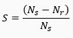
Synchronous motors operate by the interaction between a rotating magnetic field in the stator (static part) and a constant magnetic field at the rotor (rotating part).
The rotating magnetic field pulls the rotor at a constant (synchronous) speed – the speed of the rotating magnetic field, which is itself determined by the electrical frequency of the alternating current.
Slip is defined as the difference between synchronous speed and the operating speed:
Where:
S is slip, Ns is stator electrical speed, and Nr is rotor mechanical speed.
In a synchronous motor the slip is 0, as previously described. In induction motors the slip is always higher than 0 and lower than 1.
Question 37
In what case would you choose using a DC series-wound motor?
When constant operating speed is required
When precise variations in operating speed are required
When high starting torque is required
Both A and C
Explanation
In DC series-wound motors, the armature and the field windings (stationary magnet) are connected in series to the DC power source. This means that the same current flows in both the armature and the field windings.
This has several important Implications. Firstly, they have a very high starting torque. Secondly, the speed varies dramatically with the load. This also leads to poor speed regulation.
Question 38
Of the following, which is the most important factor to consider when designing motor protective switchgear?
hp
F.L.A.
S.F
The motor’s characteristics hardly affect switchgear selection
Explanation
F.L.A. (Full load amperage) indicates the motor’s expected current draw when operating at its rated load. Since the components of protective switchgear (e.g., fuses, cables, circuit breakers, overload relay cables, etc.) are characterized by their amperage, this is the factor to be considered when designing switchgear for a particular motor.
hp indicates the motor’s power output in horsepower units. While it naturally has an effect on the required switchgear, it is indirect – manifested via the motor’s F.L.A.
S.F stands for Service Factor – it is the motor’s ability to work under an increased load for a short period of time. For instance, a 7 hp motor with a 1.5 S.F. can provide 10.5 hp of power for a short amount of time.
This has an effect on another motor characteristic – S.F.A. (Service Factor Amps) – the current the motor is expected to draw when operating at this increased load. As in the case of hp, this has an indirect effect on the design of switchgear.
Question 39
What might be the cause of motor overheating?
Motor spinning idle
Reverse phase sequence
Motor operating under low load
Insufficient voltage
Explanation
When the voltage provided to a motor is reduced while operating under the same load, the electrical and mechanical variables re-balance, causing the motor to draw more current. This extra current draw results in overheating. Low voltage supply is one of the main reasons for motor overheating and can cause severe damage.
At a motor operating under low load, the lower torque demand draws less current. Therefore, the motor will normally run cooler, not hotter. That is even more true when a motor is spinning idle (under no load at all, as in a car running in “neutral”).
Reverse phase sequence (incorrectly connecting the three phases in a three-phase motor) results in the motor rotating in the opposite direction and has little to no effect on temperature.
Need extra practice? Check out the recommended Ramsay maintenance test prep course by JobTestPrep.
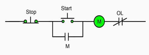
What is the purpose of the “M” contact in the following circuit?
Overload protection
Increasing the amount of electrical current through the system
Seal in contact
Timed start-up delay
Explanation
The “M” in this control circuit represents a “seal-in” or holding contact, used to maintain control voltage once the start button is released.
The other options describe roles of other circuit components:
Overload protection – overload relay
Increasing the amount of electrical current through the system – auxiliary contact
Timed start-up delay – time-delay or soft-start relay
Question 41
In a system that consists of two motors, only one should operate at any given moment. Which component is normally used to achieve that?
Interlock
VFD
Pilot indicator
Holding contact
Explanation
An interlock is a component responsible for ensuring that the operation of two separate elements is interdependent. For instance, when motor A should be turned off when motor B starts, and vice versa.
A Variable Frequency Drive (VFD) controls the frequency of the power supply, thus changing the speed and torque of AC motors. This allows for precise control over the motor speed.
A pilot indicator is an indicator that provides information about the state of a device (e.g., a little light bulb turning on when a motor is running).
A holding contact is used to maintain the current in the system once the initiating input (e.g., pushing “Start”) is removed.
Schematics and Print Reading (3 Questions)
Question 42
Fill in the blanks in the correct order:
The 10 mm diameter is a ______ with a 0.02 mm ______. The ______ is 5 mm long at a 45-degree angle. The 22 mm diameter, on the other hand, is a _______. The element also includes a 2 mm deep ________.
chamfer, diameter, undercut, recess, through hole.
through hole, radius, undercut, recess, bevel.
recess, tolerance, chamfer, through hole, undercut.
through hole, tolerance, chamfer, recess, undercut.
Explanation
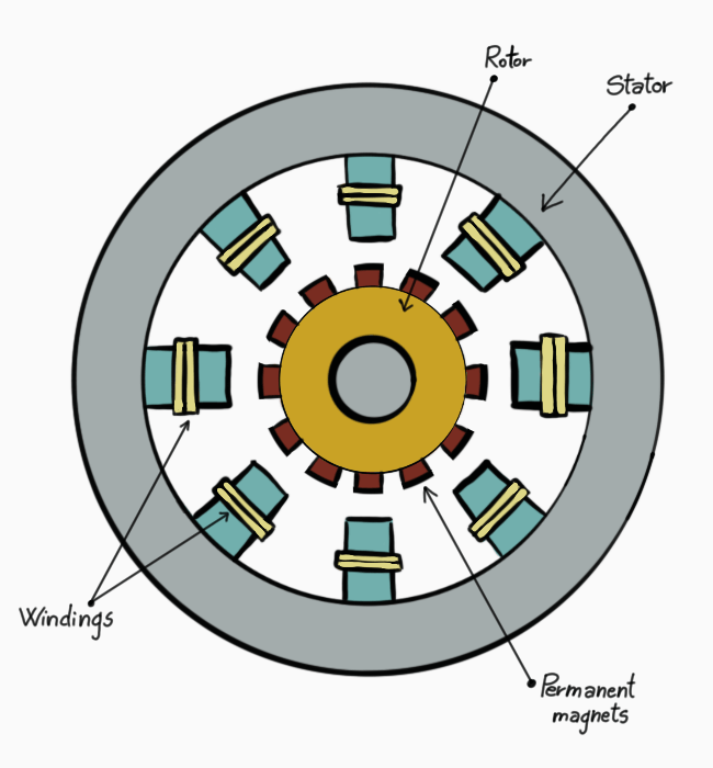
The 10 mm diameter is a through hole with a 0.02 mm tolerance. The chamferis 5 mm long at a 45-degree angle. The 22 mm diameter, on the other hand, is a recess. The element also includes a 2 mm deep undercut.
Let’s briefly explain each of the given terms, and how they relate to the print. Each element is color marked for better understanding.
Through Hole
A hole that goes entirely through the object. In the blueprint, it can be seen by the two dashed lines marked red. While these lines do not cross the element all the way through, the hole does, as it is “included” in the larger, 20 mm hole on the other side, as marked by the faint red lines.
Tolerance
The acceptable range of error an element can have from the ideal measurement. There are several ways to denote the element’s tolerance. In the case of the through hole, the tolerance is marked by a “±” symbol, marked purple in the above image.
Chamfer
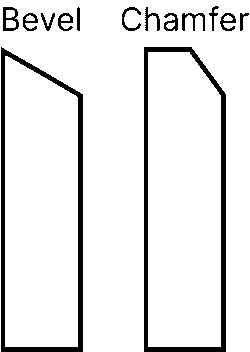
A transitional cut between two faces of an element. Sometimes used interchangeably with “bevel”, though there is a difference between them.
Chamfers extend only a portion of the entire plane between the two adjoining surfaces, while bevels extend the whole plane.
Recess
Unlike through holes, recess holes extend only a portion of the way through the element. The term “blind hole” is also sometimes used, but normally, blind holes do not have an additional hole at their bottom, as is the case here.
Undercut
An undercut is a unique recessed surface that normally cannot be accessed or machined by standard tools. Undercuts are usually relatively narrow and are often used for fastening elements during assembly.
Which diameter requires the highest level of precision?
3 mm
5 mm
10 mm
22 mm
Explanation
The diameter which requires the highest level of precision (also sometimes called “the most accurate diameter”), is the diameter where the overall tolerance is thesmallest.
The “overall tolerance” is the difference between the maximal and minimal diameter allowed. Let’s explain by inspecting the overall tolerance of each diameter in the drawing.
The drawing mentions tolerances for four diameters: 22, 10, 5, and 3.
22 mm – the tolerance is ±0.01, so (MAX – MIN) = 22.01 – 21.99 = 0.02. In short, you could say that the overall tolerance is 2 x 0.01 = 02 mm.
10 mm – similarly, the overall tolerance here is 2 x 0.02 = 04 mm.
5 mm – here, the notation is different. The top value (5.01) indicates the maximal allowed diameter, while the bottom value (5.00) indicates the minimal allowed diameter. As such, the overall tolerance is 5.01 – 5.00 = 01 mm.
3 mm – similarly, the overall tolerance here is 3.02 – 3.00 = 02 mm.
The correct answer is, therefore, the 5 mm diameter.
Digital Electronics (1 Question)
Question 45
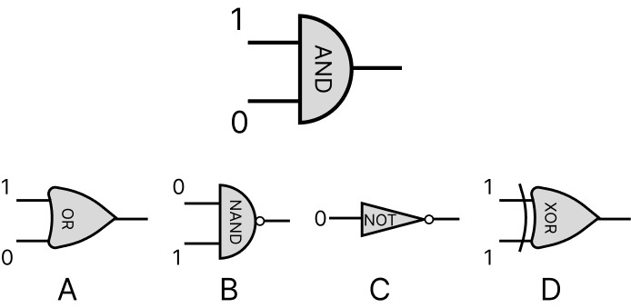
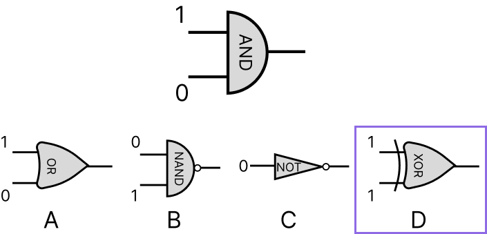
Which of the following gates has the same output as:
Explanation
The question presents an AND gate. AND returns “High” if both inputs are “High”. You may think of it as “multiplication”:
1 x 0 = 0 x 1 = 0 x 0 = 0. Only 1 x 1 = 1.
So, in our case, the output of 1 AND 0 = 0.
Let’s go over the responses. For clarity, we will not go by order.
C is a NOT gate. A Not gate simply reverses the signal from “High” (1) to “Low” (0) and vice versa.
So, in our case, NOT 0 = 1. This response is therefore incorrect.
A is an OR gate. OR returns “High” if at least one of the two inputs is “High”. You may think of it as “addition”:
1 + 0 = 0 + 1 = 1 + 1 = 1. Only 0 + 0 = 0.
So, in our case, the output of 1 OR 0 = 1. This response is therefore also incorrect.
B is a NAND gate. NAND is NOT AND, and it combines the logic of the two previous cases. In our case, the output of 0 NAND 1 = NOT (0 AND 1) = NOT 0 = 1. This response is therefore also incorrect.
Lastly, D is a XOR gate, which returns “High” if both inputs are different, and “Low” if they are the same.
0 XOR 1 = 1 XOR 0 = 1.
0 XOR 0 = 1 XOR 1 = 0.
So, in our case, the output of 1 XOR 1 = 0. This response is therefore correct.
Power Supplies (1 Question)
Question 46
What is the purpose of a rectifier in a power supply?
Increasing voltage
Converting AC to DC
Filtering noise
Regulating current
Explanation
Rectifiers are used to convert AC (alternating current) to DC (direct current).
Transformers are used to increase (or decrease) voltage, capacitators are used to filter noise, and regulators are used to regulate current.
Computers & PLC (4 Questions)
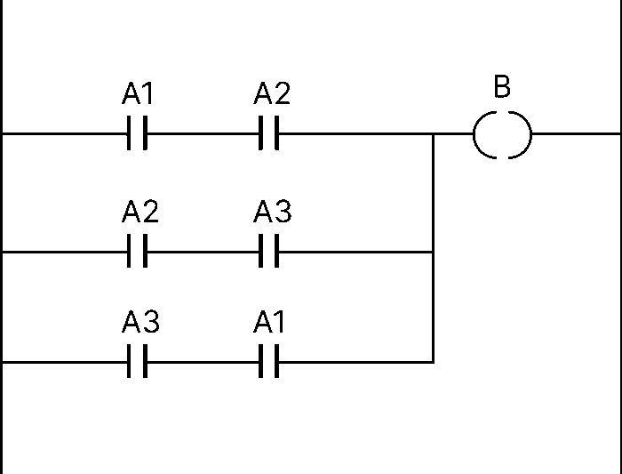
Question 47
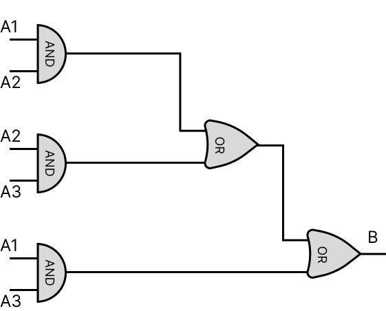
The minimal number of AND and OR gates required for the logic diagram equivalent to the PLC ladder above is:
2 AND gates and 2 OR gates
2 AND gates and 3 OR gates
3 AND gates and 2 OR gates
3 AND gates and 3 OR gates
Explanation
This question combines several basic important concepts of PLC logic. Let’s break them down.
In the PLC diagram, when the input of any pair is true (A1 + A2 or A2 + A3, or A1 + A3) is true, the output in B is also true.
We can break that logic down into two parts:
The signal of both detectors on the same rung should be true for the output of the branch to be true. (Equivalent logical gate: AND).
If there is at least one true signal from one of the rungs, the overall output at B is true. (Equivalent logical gate: OR).
This is why, generally speaking, AND is equivalent contacts in series, whereas OR is equivalent to contacts in parallel.
So, the equivalent logic, gate-level diagram is:
However, remembering that OR gates are associative and commutative, we may group the inputs for simplification and reduce the number of OR gates to 2:
Note that the nature of the AND gate, which requires both conditions to be true, does not allow us to combine gates as with an OR gate, so three AND gates are required.
As such, the minimal equivalent diagram will include 2 OR gates and 3 AND gates.
Question 48
In a PLC diagram, an N.C. contact could represent:
A start button
An emergency stop button
A gas detector in a furnace
Both B and C are correct
Explanation
In normally closed (N.C.) contacts, when the condition is true, the contact is open, and the output flow is blocked. When the condition is false, the contact is closed, and the output flow is uninterrupted.
More simply put, in a NC contact, if there is no signal, “everything is normal”, and if there is signal, “something is wrong”.
This makes N.C. contacts a proper choice for devices whose purpose is to stop or trip the control circuit when activated – such as an emergency stop button.
A start button should be activated for the device to work, and not the other way around, so start buttons are normally open.
Similarly, the purpose of gas detectors is to allow the operation of a furnace only when gas is detected (i.e., the signal is true).
Question 49
In ladder logic, the leftmost elements should normally be:
Safety and stop interlocks
Complex logic elements (e.g., timers)
Output coil
The order of the elements along the rung does not matter
Explanation
PLC ladder diagrams are read left to right, top to bottom. As for “left-to-right”, this means two things:
Visual convention – the current flows through the left elements first.
Reading order – The CPU unit of the PLC evaluates the logic in that order.
This is why the most important elements (i.e., safety elements) should be prioritized and gate everything that follows – thus govern the functioning of the entire system.
On the other hand, complex, data-modifying elements should be placed further to the right of the diagram.
The output coil, which receives the “final” result of all contacts, should therefore placed on the far-right end of the diagram.
Question 50
Fill in the blanks correctly:
When terminating a _______ ethernet cable through an RJ45 connector, you should use _________ on __________.
Straight through, T568A or T568B, both sides.
Crossover, T568A or T568B, both sides.
Straight through, T568A on one side and T568B on the other.
Crossover, only T568B, both sides.
Explanation
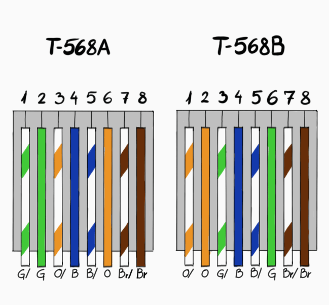
T568A and T568B are color wiring schemes for eight-position connectors.
For instance, this is the pinout diagram of an RJ45 with the T568A scheme:
While T568B is more modern, both are valid standards.
A straight-through cable has the same scheme on both sides, while a crossover cable has a different scheme on each side. This means that of the given options, the only correct answer is A:
When terminating a straight through ethernet cable through an RJ45 connector, you should use T568A or T568B on both sides.
Test Instruments (2 Questions)
Question 51
When using a clamp meter to measure AC current:
Clamp the hot and neutral wires together
Clamp only one wire at a time
Ground the meter before measurement
Both B and C
Explanation
A clamp meter detects the magnetic field around electric wires to measure the current. As such, it must be clamped around only one of the conductors (hot or neutral). Measuring more than one conductor (like hot + neutral) causes the opposite magnetic fields to cancel each other out and produces a reading of 0.
To do so, one should either physically split the wires, or (preferably) use a line splitter. Answer D is incorrect since clamp meters are not grounded — they’re isolated sensing devices.
Question 52
What does a beep typically indicate when using a multimeter in continuity mode?
An open circuit between measured points
High resistance between measured points
Low resistance between measured points
Voltage difference between measured points
Explanation
Continuity mode is designed to measure the uninterrupted electrical flow between two measured points. When a beep is heard, it indicates that such flow exists – i.e., low to no electrical resistance.
Basic AC/DC Theory (3 Questions)
Question 53
What is the power in the following circuit?
6W
12W
24W
48W
Explanation
According to Ohm’s Law:
V = I x R
And
P = V x I
Therefore, P = I2 x R.
In the given circuit:
P = 22 x 12 = 48W
Question 54
A sinusoidal AC wave has a peak value of 220 V and an RMS of 155 V. What is the wave’s frequency?
1.4 Hz
65 Hz
110 Hz
Cannot be determined
Explanation
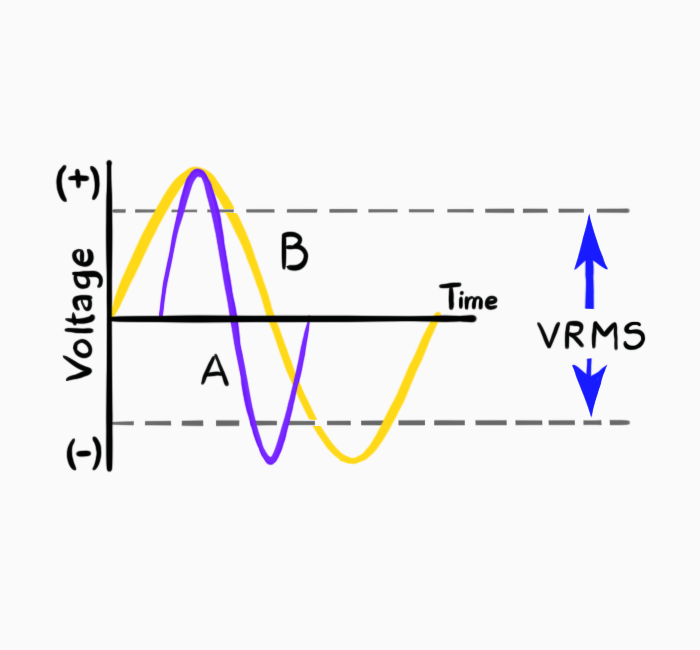
This is a trick question.
In a sinusoidal wave, the RMS and peak value are related, but not the frequency. That is derived directly from the very definition of the RMS (Root Mean Square) – the “average” value of a fluctuating signal.
Example: Two waves of same peak values (A and B) have different frequencies but the same RMS.
This can also be seen in the basic formula for RMS in a sinusoidal wave:
Where:
VRMS is the RMS value
VP is the peak value
Question 55
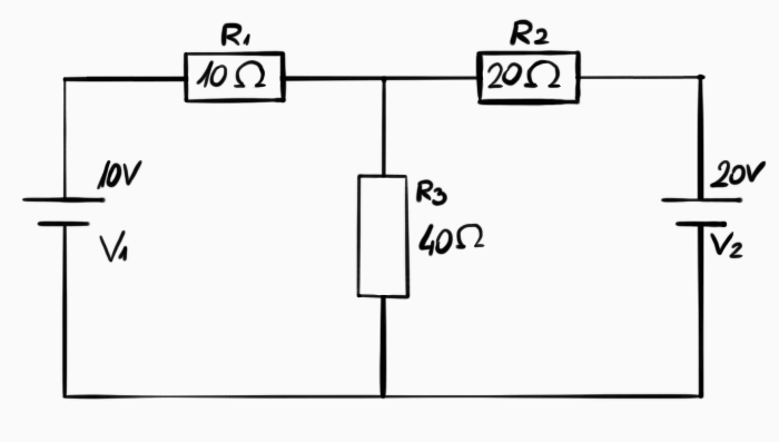
What current flows through resistor 3 in the following circuit?
0.143 A
0.286A
0.347 A
0.429 A
Explanation
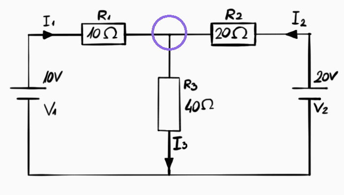
This is a classic, basic question in mesh current analysis, based on Kirchoff’s Laws:
Kirchoff’s Current Law – The sum of currents on a particular point equals 0 (that also takes into account the direction of the current – see below).
Kirchoff’s Voltage Law – The sum of voltages on any closed loop equals 0.
Here’s a step-by-step process:
Step 1 – Determine Currents and Directions
Firstly, we will define arbitrary directions for the current flowing through each resistor (I1, I2, I3):
Step 2 – Current Equations (1st Law)
In the given question, there is only one point through which more than one current flows.
So, the equation is:
(i) I1 + I2 – I3 = 0
I1 and I2 enter the point, so they are positive, while I3 leaves the point, so it is negative.
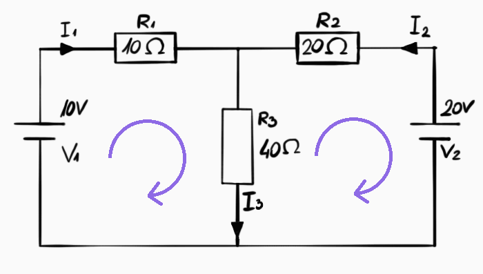
Step 3 – Voltage Equations (2nd Law)
This time, we have two closed loops on which to calculate voltages.
Summing the voltages and equating to zero yields two equations:
(ii) 10 – R1 x I1 – R3 x I3 = 0 -> 10I1 + 40I3 = 10
(iii) 20 – R2 x I2 – R3 x I3 = 0 -> 20I2 + 40I3 = 20
Note that according to Ohm’s Law: I x R = V.
Plugging equation (i) into (ii) and (iii), and simplifying, we get:
5I1 + 4I2 = 1
2I1 + 3I2 = 1
Solving these two linear equations yields:
I1 = -0.143 A
I2 = 0.429 A
I3 = 0.286 A
Note that the minus sign indicates that the direction of the current is opposite to what we have assumed. In our case, it means that I2 flows right-to-left and not left-to-right. However, the magnitude of the current is what we’re interested in, and that answer will be correct as long as you are consistent.
Power Distribution (2 Questions)
Question 56
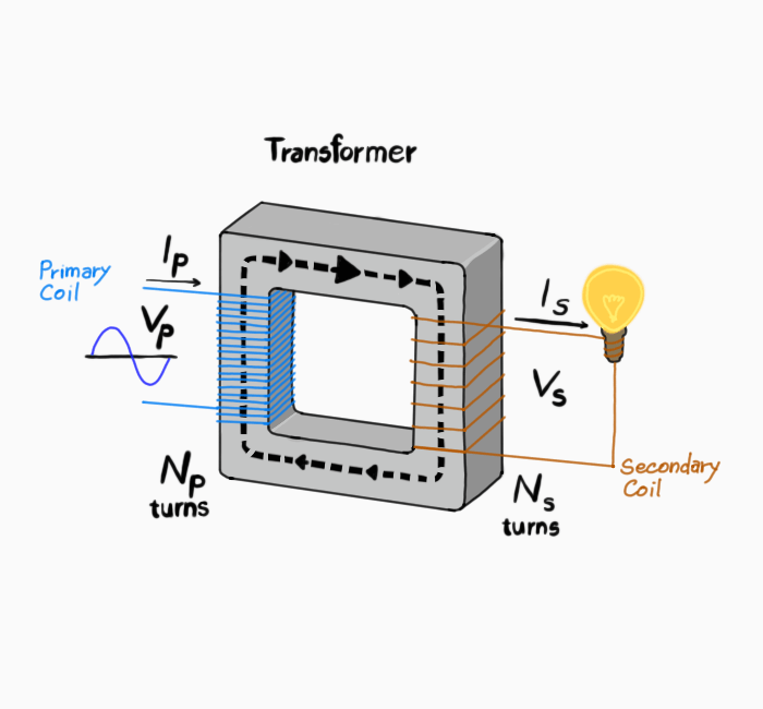
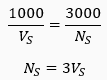
A step-down transformer has 3000 turns on the primary coil. The primary voltage is 1000 V. This means that the secondary coil could have _____ turns and that the secondary voltage is ____ V.
300, 1000
300, 100
6000, 2000
Both B and C are correct
Explanation
Transformers are used to transform high AC voltage to low voltage, or vice versa. They are rather basic devices, constructed of an iron core and two coils – a primary coil and a secondary coil.
The primary voltage in the primary coil is transferred into the secondary coil. The ration between the voltages is determined by the ratio of turns in both coils:
Where:
Np – Number of turns in primary coil
Ns – Number of turns in secondary coil
Vp – Primary voltage
Vs – Secondary voltage
In our case, the known values are Np = 3000, Vp = 1000:
Now, since we deal with rations, there can be an infinite number of values to satisfy the equation. Of the given options, both B and C do.
However, the question states that the given transformer is a “step-down” transformer. This means that the transformer reduces the voltage (i.e. Vs < Vp). This means that answer C is incorrect, and only answer B applies.
Question 57
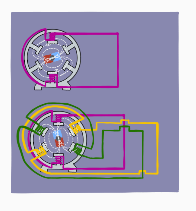
Transferring a single-phase system into a 3-phase system will NOT allow:
Reduced conductor size
Increased power
Reduced overall wiring length
Stabler output power
Explanation
In a single-phase power supply system, the current flows through a single wire in one phase. In a 3-phase power system, on the other hand, the current flows through 3 or 4 wires in three different phases, as seen in the images below.
This, naturally, requires more wiring.
This structure gives 3-phase power systems a variety of advantages over single-phase systems. Let’s break down the major ones:
Advantage #1 – Increased Power
Perhaps the main advantage of a 3-phase power system is the ability to produce more power under the same current. Generally speaking, the power produced from a 3-phase system with current I is 73% higher than that of a comparable single-phase system.
We will not get into a full explanation here, but it is enough to say that this characteristic is derived from the vector geometry of the 3-phase system, and represented in the power formulas:
Single-Phase System Power Formula
3-Phase System Power Formula (for a balanced load with 120 degrees phase angle)
I is the line current
V is the line voltage
Cos(Φ) is the power factor
The √3 factor comes, as we have previously mentioned, from the vector geometry of the three phases. √3 is approximately 1.73, hence the 73% power increase previously mentioned.
All in all, the 3-phase system allows higher power under similar current.
Advantage #2 – Reduced Conductor Size
As we have just seen, transferring the power system into a 3-phase system allows us to produce the same power under lower current.
Since conductor size is generally determined by current, reducing the current means lower conductor size.
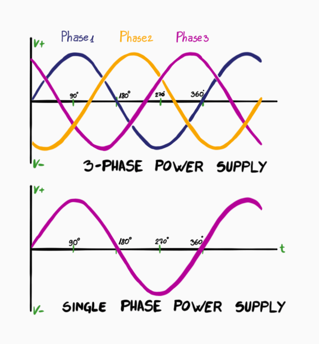
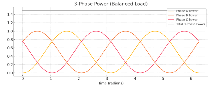
Advantage #3 – More Stable Power Output
In a single-phase power system, the power fluctuates in a sinusoidal wave. Alternatively, in a 3-phase system, while the power of each phase fluctuates similarly, the sum of these three phases is constant at any point, as seen in the picture below:
This allows steadier power output.
Electrical Maintenance (3 Questions)
Question 58
Which of the following faults cannot be detected using infrared electrical inspection?
Open circuits
Loose connections
Overloaded circuits
None of the above
Explanation
Infrared electrical inspection reveals defects in electrical components by detecting “hot spots”. These hot spots indicate high resistance, and hence, high current and excess heat.
As such, defects and issues such as loose connections and overloaded circuits are easily detected, while open circuits (where no current flows) will not show anything abnormal.
Question 59
Which of the following components needs to be discharged before performing maintenance?
Resistors
Relays
Transformers
Capacitators
Explanation
Capacitators are used to store electric charge and hence must be discharged before undergoing maintenance. Resistors, relays, and transformers do not store charge.
It is necessary to ensure that all electrical elements are de-energized before maintenance, but of the options given, only capacitators should be actively discharged.
Question 60
A circuit breaker has tripped. What should you do immediately afterwards?
Replace the breaker with a higher rated one
Inspect the circuit for overload or other faults
Reset the breaker
Wire a bypass around the breaker
Explanation
Circuit breakers are designed to protect electrical components from excess current. Therefore, when a circuit breaker trips, it normally indicates there is a problem with the circuit causing such excess current.
Simply resetting the breaker is likely to cause the problem to repeat itself and does not address the core issue.
Similarly, replacing the breaker with a higher rated one (i.e., capable of handling higher current) or wiring a bypass around it undermine the very purpose of the breaker. These actions are, therefore, highly unsafe.
Need extra practice? Check out the recommended Ramsay maintenance test prep course by JobTestPrep.
Full Disclosure: I am affiliated with JobTestPrep. Clicking the links helps me provide you with high-quality, ad-free content.
Large Practice Volume
The preparation contains over 400 practice questions in a variety of topics, creating the most comprehensive Ramsay preparation available.
What Do You Get?
7 full-length simulations
400+ Ramsay-style questions
Detailed answers & score reports
5 comprehensive study guides
Authentic Mock Tests
Each practice test on JobTestPrep’s preparation pack accurately simulates the actual Ramsay Test in terms of the topic list, question format, and level of difficulty.
Detailed Explanations + Guides
Each question is accompanied by a detailed explanation written by subject matter experts. Five PDF guides complement the practice tests.
Randomized Tests (Optional)
The randomized tests will add extra challenge and provide an effective summary drill.